|
My Model T Fordbreaks her crank.The rebuild continues.......
Another weekend dedicated to my Model T Ford proved to be interesting on a number of fronts. Whilst the block is away being rebabbited, we decided to pay some attention to the transmission. As we began the disassembly, the simplicity of the transmission revealed just how robust the Model T Ford really is.
Our first discovery was that the car, although reported to me when bought, was not in fact fitted with a Jack Rabbit clutch at all. Inside, a standard Model T Ford clutch assembly of steel discs. Some of these were showing blueing where the discs at some stage have become very hot. I was a little suprised and disappointed not to find the Jack Rabbit clutch, but equally impressed at how little trouble the standard clutch had given, even on the coldest mornings. At the same time, we discovered the clutch drum locking bolt was not only missing any split pin or locking wire, but also barely even finger tight, fortunately another potential disaster avoided.
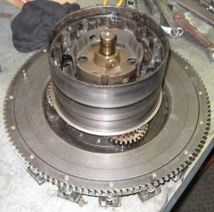
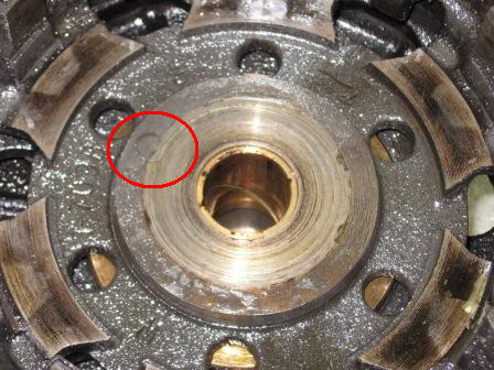
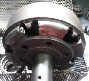
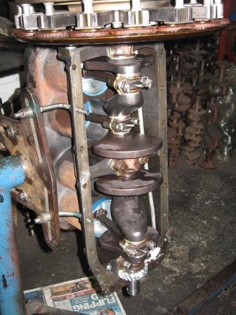
With the transmission drums lifted off the engine flywheel, the brake drum was inspected and instantly showed a loose rivet as can be seen above. This will have to be repaired before reassembly.
After a clean in the spin washer, the transmission drums were then inspected for cracks and I'm pleased to say that none were present.
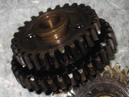
When we started the engine rebuild, we had already identified that at least one of the transmission triple gear bushes was quite worn. Even so, the transmission always worked well, wth no vibration of undue noises. Inspection of the triple gear revealed in this one shown above, that the bush was barely fitting the gear, easily able to be pushed out by finger. Next we moved to the Magneto. Disassembling the Model T Ford Magneto
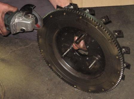
With the transmission assembly removed, the first step was to grind off the peened over ends of the Magneto clamping screws. These are to be replaced, and, as a matter of course, should always be replaced after a disassembly. Using old screws is false economy should one come loose, the damage can be catastrophic. The brass Magneto screws not only clamp the magneto magnets in place, but also hold the ring gear onto the flywheel as well in cars fitted with starter motors. As my ring gear is badly worn in places, it is also to be replaced. When the screws were removed, the ring simply slipped off the flywheel.
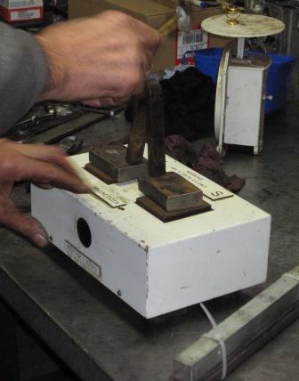
My magneto had worked well the entire time I have owned the car, so I was quite suprised to see just how weak the magnets were. It was quite fortunate that a friend from our club was in town and had brought his magnetiser with him. After a few "zaps and taps" the performance increase in the magnets was quite amazing, with each now capable of lifting between 7 & 8 pounds of weight, far in excess of the minimum requirement of 2. With the magnets recharged, they have been stored until the engine rebuild gets underway.
Refitting the new crank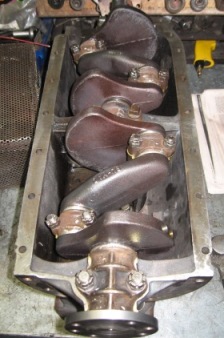
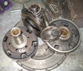
Whilst the engine was away being rebabbited, the transmission components were put through a heated spin washer to clean them up.
This 'pile of bits' will soon be reassembled once new triple gear bushes are fitted and a loose rivet fixed.
Assembling the Ford MagnetoWith the Australian National Model T Rally in recent weeks, progress has been a little slow, but we have some updates to share. With SIX more broken crankshafts as a result of the challenging country toured, it seems many others will be doing similar work to me.
With the bolts lightly tightened, the magnets sit up to allow the cotton reels to be fitted between the magnet poles and the flywheel. The locking plates were sat on top, then NEW brass magnet screws installed. For such a minimal cost, I just can't see why anyone would risk their magneto once the engine was fitted, by using old screws.
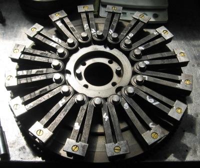
As my car is a 1927 model, it is fitted with a starter. This means that the magnet retaining screws also hold the ring gear for the starter onto the flywheel as well, so when fitting the screws, it is necessary to ensure the threads for the ring gear are aligned as well. The next step is to check the magnet heights. It is imperative that the magnets all sit at the correct same height, providing between .025 and .040" clearance to the coil or bobbin plate. Bear in mind that the clearance is affected by crankshaft end play. The magnets spin past each of the 16 coils and must have the same clearance to ensure that a strong and even current is induced, providing the ignition power. This clearance can be time consuming to achieve, but the investment in the KR Wilson Magneto gap tool has proved invaluable to my engine builder. Balancing ComponentsOne of the keys to a smooth running and long lived engine is the balancing of all reciprocating parts. The Model T is challenged by its very design in that it has a huge weight (flywheel and transmission) hanging off one end and an insignificant weight (the fan pulley) on the other. Here we have balanced the clutch/brake drum assembly and have had to removeda small amount of weight off the casting.
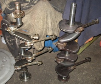
Here you can see the considerable difference between a new counterbalanced crankshaft and the original Ford Model T crankshaft.
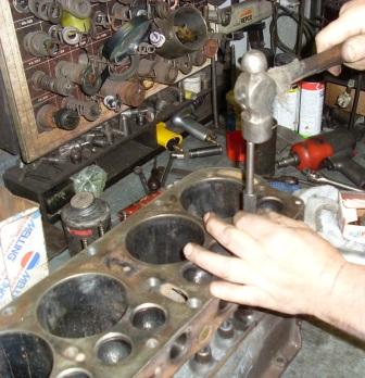
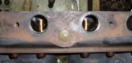
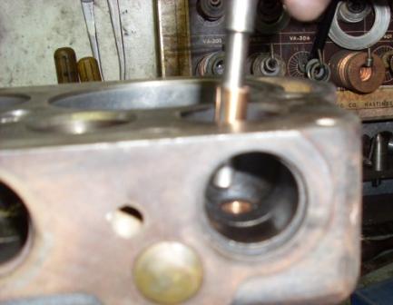
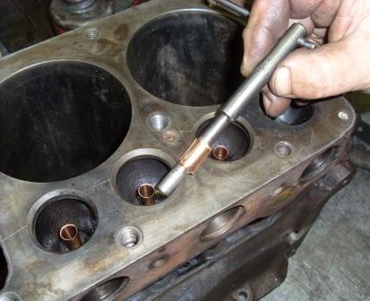
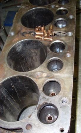
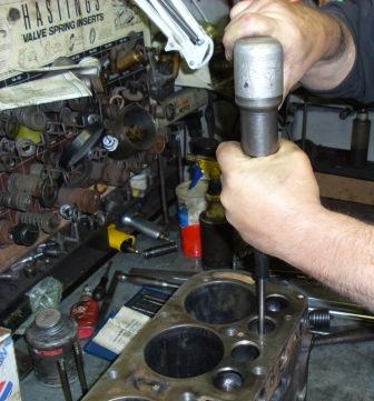
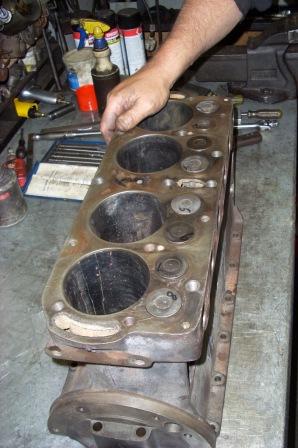
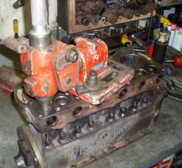
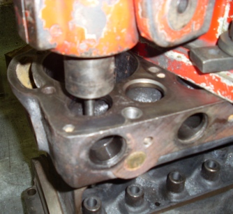
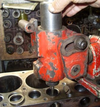
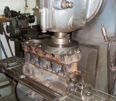
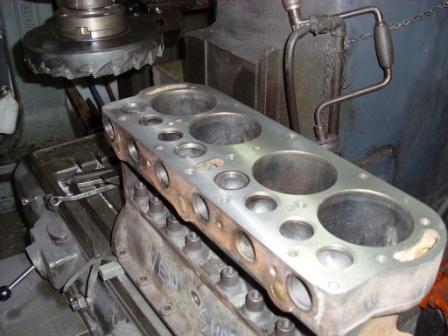
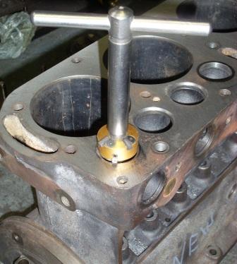
Completing valve workWhen my Model T engine was broken down, we discovered that it had done a fair bit of work, even though the engine had clearly been 'reconditioned' in recent years. I already knew that the engine was fitted with better quality Holden valves (Holden is the Australian division of GM)and also knew that at least one was sitting a little low in the block as a result of wear. What we discovered was around 6 thou of wear in the valve guides. Far too much for comfort, so we decided to sort them out and avoid having to do it later. The following photos show the step of fitting, cutting and broaching K Lines, the cutting of the block to fit new hardened valve seats and the cutting of those inserts to mate with the valves. Not shown is the step preceeding this work where the original guides are reamed out to take the new K Line inserts. Hover your mouse pointer over each photo for a description of each step.
Fitting hardened valve seats
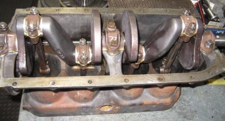
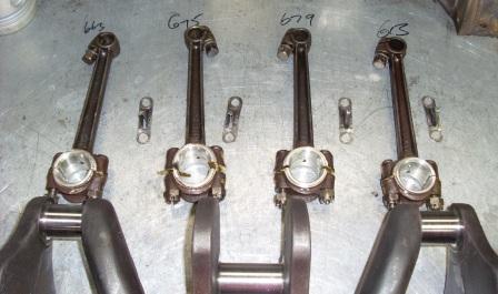
Here we have laid out the conrods and are checking the weight of each. This will help us make sure that they are as balanced as much as possible. Unfortunately for us, three of the four rods were within a few grams of each other, not needing any work, but the fourth, the lightest, came in at nearly 2 ounces lighter than all the others. This meant that a fair bit of weight had to be removed from the other three to bring them closer.
2011 UpdateWith the new year underway, the engine rebuild has progressed well and is almost finished. Since the last update, the bottom end of the engine has been assembled into the block and the valve gear and magneto assembled onto the block and crank.
Click here to continue reading the final installments of the engine rebuild in 2011 Click here to return to Model T Ford rebuild page 1
|
