|
Model T FordTransmission Components
The Model T transmission is perhaps the least understood parts of the Model T Ford. In all the research I've done, the transmission seems to have the least amount of explanation available, or, well at least not in "lay" terms, simple, for the non mechanically minded. So, here's my effort at explaining just what goes on. It assumes a basic understanding of mechanical components, so if you don't have this, let me know and I'll see if I can fill in any blanks. I've done the above animated diagram to help those of us that need to visualise things to get an understanding. The first thing to do is understand the different components so that you can make the link between the explanation and the component and its action. Lets start at the flywheel at the back of the engine. 
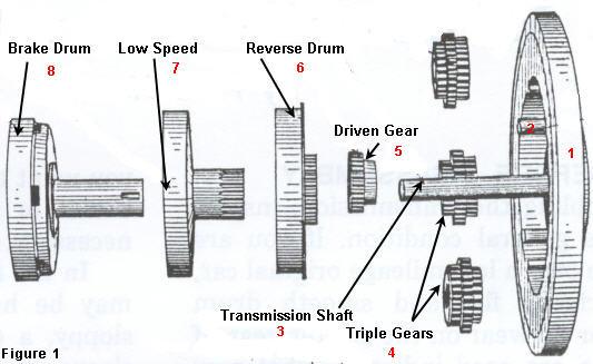
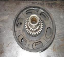
The Flywheel (fig 1, #1) obviously provides the motion that is transferred through the transmission. It provides the transmission shaft mounting(fig 1 #3) (that the rest of the main components rotate on) and three small shafts or pins (fig1 #2), that the triple gears rotate on. As mentioned, the Triple gears (fig 1 #4) mount on their pins with the flywheel, rotating with it, but also able to rotate on their own pins in either direction at the same time as they rotate with the flywheel. (Picture how the Earth rotates on its axis, as well as rotating around the sun at the same time, hence the term Planetary transmission) The Triple gears are named, not just because there are 3 of them, but also because each one has three different numbers of rings of gear teeth or ratios. Next in line is the driven gear (fig 1 #5), this is mounted on the transmission shaft against the flywheel, but not "locked" with it, so that it can spin independently of the shaft/flywheel.(its locked to the brake drum, but we'll get to that later) The Driven gear is meshed with the first set of gear teeth on the Triple gears (see fig 3 below), closest to the flywheel. (think of the driven gear as the sun, and the triple gears the planets spinning around it) Next we have the reverse speed drum and gear (fig 1 #6). The reverse drum gear is fixed, so whatever the gear does, the drum does. This drum slides onto the transmission shaft, and the gear meshes with the triple gear teeth set that are furthest from the flywheel. Next in-line is the low speed drum and gear (fig 1 #7), this gear also fixed to its drum, protudes further out from the drum than the one on the reverse drum, this is because it passes through the centre of the reverse drum and gear, Next in the assembly is the brake drum (fig 1 #8). The brake drum also rotates on the transmission shaft, but has no gear teeth. Instead, it has an "extension" that passes through both the low speed drum, and reverse speed drum with a keyway that is used to lock the driven gear to it. This means that whatever the driven gear does, the brake drum does. The brake drum provides a "housing" within which the next component fits, the clutch disc drum (fig 2 #1) and discs (fig 2 #2).
ModelT
The clutch assembly provides the physical "break" between the action of the engine and the rear axle, without it, the car would always be moving when the engine was running.
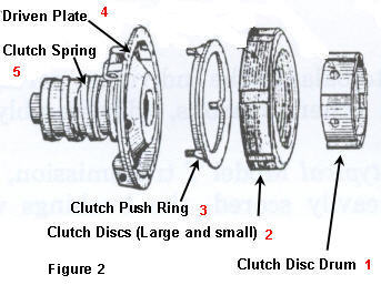
The clutch is comprised of two sets of different sized steel discs. The larger set have recesses in their circumference that engage with lugs on the inside of the brake drum, so that these discs do whatever the brake drum does. In between each larger disc is a small disc that engages with the clutch disc drum, these are sandwiched and rely on engine oil to provide lubrication and prevent wear. The clutch disc drum is fixed to the end of the transmission shaft and therefore rotates with it, as do the small clutch discs. The next part of the assembly is the clutch push ring, this as its description suggests, pushes against the clutch discs and it in turn is acted on by the driving plate and clutch fingers.
The driving plate (fig 2 #4) provides the physical link between the driveshaft and rear axle. It is bolted to the brake drum and therefore connected to the driven gear. It also comprises the clutch spring (fig 2 #5), the spring providing clamping pressure which is "magnified" by the lever action of the clutch fingers and "sandwiches" the inner and outer clutch discs together when required by passing pressure onto the push ring (fig 2 #3) through holes in the driving plate.
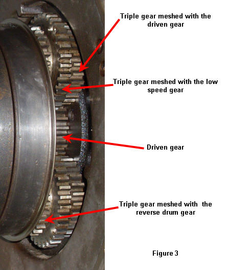
Figure 3 shows the entire drum assembly mounted with all the triple gears, driven gear and transmission gears meshed and mounted to the flywheel. Externally, the transmission controls are three floor pedals, one for the low speed drum (and high speed/clutch control), one for the reverse speed drum and one for the brake drum. In addition the emergency brake lever. This provides two actions, it pulls on the rear emergency brakes as well as acting on the clutch spring, either allowing or preventing the spring from acting on the clutch discs.
Each floor pedal clamps a transmission band around the outside surface of its respective drum, the action of which is explained next. Before proceeding however, it is important to note that the low/high speed pedal also acts to disengage the clutch spring pressure (as does the handbrake lever) when held in the "neutral position"
Why are donations needed? Read why here. How the transmission worksSo lets look at how everything works, remembering these simple rules:
With the engine running and the car standing still the following happens: The car is stationary, which means the driving plate is stationary because it is permanently fixed to the driveshaft and rear axle.
The reason the engine can still run is because the link follows this:
In the following animation, the gears that are attached to the drums are shown only as an example of the number of gear teeth, action and direction of rotation when a gear is selected.
Low Speed When the driver wishes to move off (forwards), the emergency brake is released halfway (to allow the rear wheels to turn), but still preventing the clutch spring to clamp the discs together. (obviously you can't just "drop" the car into high gear as it would stall the engine - although this is physically possible Click on the handbrake in the animation above, then click on the low speed pedal and see what the gears do." When the driver wishes to move in reverse, the emergency brake must be released. The emergency brake is released halfway (to allow the rear wheels to turn), but still preventing the clutch spring clamping the discs together. when the driver wishes to engage high gear (direct drive), the emergency brake lever must be released fully forward (whilst the low pedal is either held halfway or fully depressed engaging low gear) so that it no longer prevents the clutch spring from compressing the clutch discs. As the car speed is increased, ready to shift to high gear, the driver momentarily lowers the engine revs and simultaneously releases the low gear pedal (and therefore the last resistance holding the clutch spring back), this allows the clutch spring to apply full pressure to the discs, clamping the small discs between the large discs. Now remember that the small discs are directly fixed to the disc drum and therefore transmission shaft and flywheel, and, the large discs are fixed to the brake drum and therefore driven plate. So the action of clampng the two together, provides a direct link as follows:
Click on the handbrake to put it in the fully forward position and then click on the low/high speed pedal to engage high gear. and see the gears in direct drive. When the driver wishes to stop (without stalling the engine), either the emergency brake lever or low speed pedal must be changed, handbrake pulled back or pedal pushed halfway to release the clutch spring pressure off the clutch discs and freeing the direct connection between the engine and rear axle, then (or simultaneously) apply the brake pedal. Click on the handbrake once to disengage the clutch, then click on the brake pedal and see the action on the driven gear> Return to Model T Central Transmission Specifications
|
 further than the reverse gear and therefore able to mesh with the second set of teeth on the triple gears. See figure 3 below to see the relationship between each gear. (note, it's not really necessary to understand why they are aligned this way, suffice to say its to ensure the gear ratios work and allow the right motions to occur when required)


